Section 02 · The Chamber E-07
Emission in a sealed box
A specimen in a chamber with controlled temperature, humidity and air exchange, sampled at intervals to give a rate rather than a level.
Why the box exists
A concentration measured in a room tells you what was in the air at that moment. It does not tell you which surface put it there, at what rate, or what the number would be in a different room with different ventilation. The sealed chamber exists to answer a more tractable question: how much does this specimen emit, per unit area, per unit time, under defined conditions?
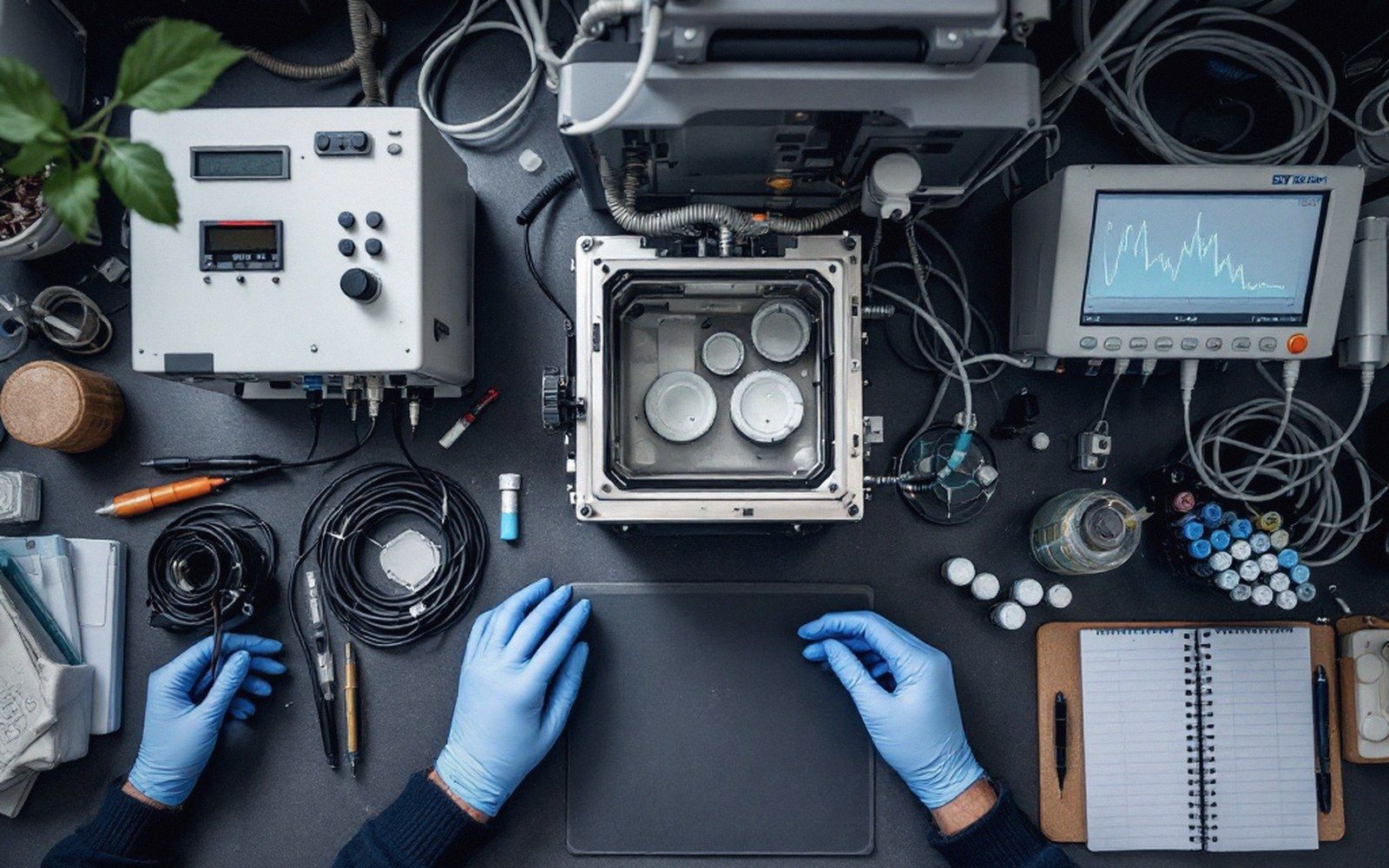
The logic is containment. A test specimen — a floor tile, a length of wall panel, a cut of adhesive-bonded board — is placed inside an enclosure of known volume. Temperature, relative humidity and the rate at which clean air is exchanged for the chamber air are held constant throughout the test. Air leaving the chamber is sampled at one or more intervals, the analytes captured on sorbent tubes and taken to the laboratory. What comes back is not a snapshot of a room but a material-specific emission rate that, in principle, travels with the material wherever it is used.
The key output is the specific emission rate, commonly expressed in micrograms per square metre per hour (µg/m²·h). To reach it, the laboratory combines three things: the concentration measured in the outflowing air, the volumetric flow rate of that air, and the exposed surface area of the specimen. Divide the mass of analyte leaving per hour by the surface area and the units reduce cleanly. That figure is then the material's number — not a building's number, not a room's number. How it translates back into a room concentration depends on the area-specific rate and the ventilation conditions of the space where the material will actually be used.
What the chamber controls
Three parameters dominate. Temperature, typically set at 23 °C for general building-product testing, drives emission: a higher temperature increases the vapour pressure of volatile compounds and speeds diffusion through the material matrix. Relative humidity, often held at 50 %, matters both for hygroscopic materials and for compounds whose release is partly hydrolytic. The air change rate — expressed as the number of chamber volumes exchanged per hour — sets the dilution the emitted compound experiences. Lower air change rates allow concentrations to build; higher rates keep the chamber closer to a steady-state sink-free condition. European chamber test standards, including EN ISO 16000-9 for general VOC testing of building products, specify these parameters explicitly, and any report that does not state the operating conditions of the chamber is incomplete.
Chamber size is not arbitrary. Small chambers, on the order of a few litres, suit small specimens and short-chain compounds. Larger chambers — one cubic metre is a common reference size — are used when the specimen needs to be tested at its installation dimensions or when the test is intended to simulate whole-room loading. The ratio of specimen surface area to chamber volume, the so-called loading factor, is set by the standard and determines how representative the result is. Change the loading factor and you change the steady-state concentration even if the emission rate of the material is identical.
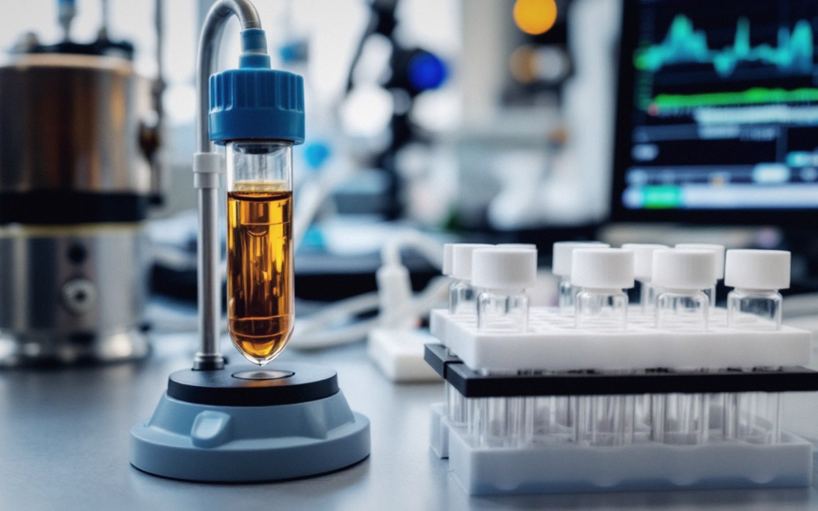
Sampling happens at the chamber outlet. The outflowing air passes through pumped sorbent tubes at a controlled flow rate; the volume drawn, combined with the measured concentration, gives the mass of analyte collected in that interval. Multiple sampling points across the test duration — day three, day seven, day twenty-eight are typical milestones under EN ISO 16000-9 — trace how emission falls over time. A single-point measurement is rarely sufficient. The decay curve that emerges matters: a material that shows high initial emission dropping sharply behaves very differently in a building from one that emits at a lower but sustained rate over months.
Background chambers run in parallel, loaded with no specimen, to establish the blank contribution from the chamber walls, the air supply and the tubing. That blank is subtracted before the emission rate is calculated. Without it, there is no way to separate what the material emitted from what the apparatus contributed.
The sealed-box result is a laboratory artefact in the best sense: a controlled, reproducible, transferable number. Its limitation is that no real room is a chamber, and the conversion from material rate to room concentration requires assumptions about geometry, ventilation and how surfaces interact with each other. The chamber produces the input; the building model does the rest.
Filed inSection 02 — The Chamber